Learning how to solder is a great asset to an audio engineer, musician, audiophile or home studio owner. Being able to make and repair your own cables can get you out of a tight spot and save you money. We are going to go through the basics of soldering and the tutorial will focus on soldering a standard TRS jack connector to a length of balanced audio cable. (3 core mic/line cable)
Required Tools
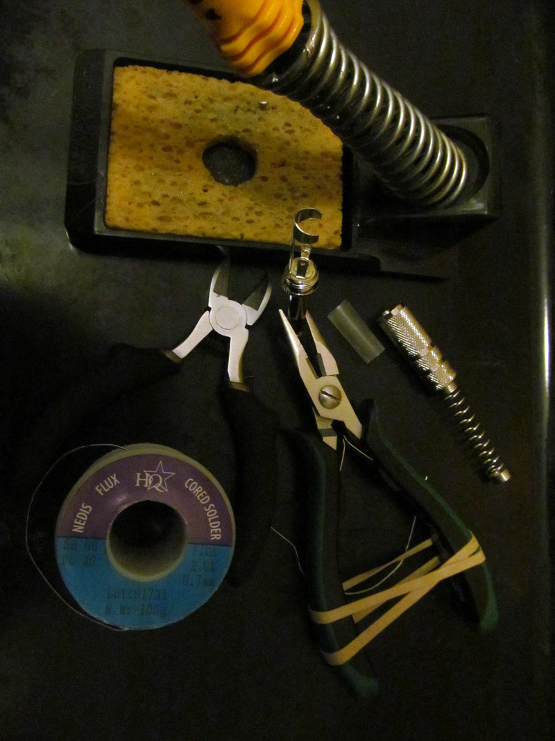
- Soldering iron of 25 watts + power rating
- Soldering iron holder
- Damp soldering iron tip cleaning pad (often a sponge one supplied with iron holder)
- Wire stripper/cutter
- Solder
- Cable and connector
Tools that will greatly assist
“3rd helping hand” — a soldering specific weighted base with metal arms and crocodile clips. Alternatively, a pair of pliers with an elastic band around the handles to hold the grip without physically holding the pliers handles (the use for this will become clear when you practice soldering).
A cable tester or standard multimeter with continuity test function will also be useful.
Preparation for a soldering job
The first thing to do is collate all of the tools you need onto a table top, it is a good plan to have a fireproof/heat resistant tray of some kind on the table for the area where you wish to solder. I like to use an old baking tray. Place your soldering iron in its holder and start heating the iron, never leave the iron unattended when it is on and keep plenty of space free around the iron itself. It usually takes a soldering iron some 3-4 minutes to reach operating temperature.
Take your TRS connector and unscrew it and take a look at the solder tags inside the connector housing. Each TRS connector will have a slightly different soldering tag arrangement. Some have a flat surface and some small lugs with a ring eyelet for a piece of cable to attach. It is a good plan to get familiar with the layout of the solder tags in each and every connector you plan to solder. For each different connector type, like an XLR for example you will need to get an eye for how far into the housing they are. This is important as you will need to be able to become good at estimating how much outer cable sheath (insulation) to strip off so the cable that remains unstripped will successfully meet with the connectors ‘strain relief’ type.
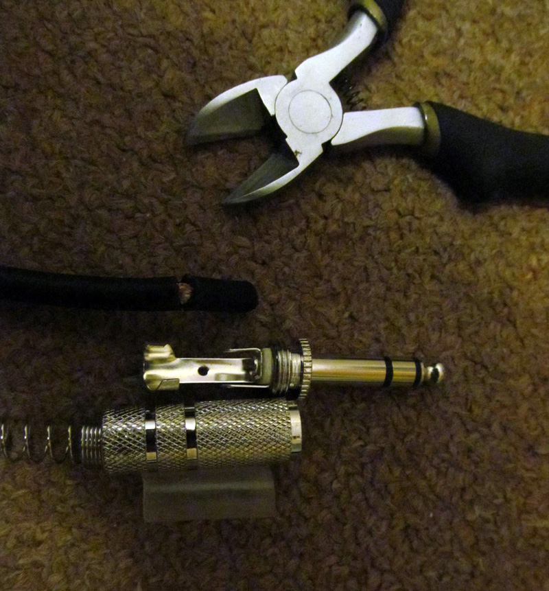 This photo (on right) approximates where to remove the black outer sheath from the cable for the connector shown. (indicated by the cut in the outer sheath exposing the copper inside)
When cutting into or stripping the outer sheath take care to only cut into the outer sheath and do not cut so far in as to damage the inner cables. This is easy to do for a novice so practice this several times.
Remove the outer sheath completely and inside the balanced audio cable there are 3 smaller inner cables: positive, negative (insulated) and earth — the earth does not have a secondary layer of insulation like the positive and negative signal cables and is wrapped around the inner 2 cables. There is often a piece of string like material inside the outer sheath which helps keep the relative positions of the internal cables, you can trim this back with your strippers/cutters as it usually gets in the way.
 Strip a very small amount of the internal wires insulation off, this is ideally 3-4 mm for an TRS jack audio connector (5 mm for an XLR). This can be fiddly for a novice as getting the right amount of grip without cutting through the cable can be initially awkward. Try experimenting a few times, as we know practice makes perfect. Your cable should look like photo on right.
Starting the soldering process
A very important technique in soldering is known as ‘tinning’. Tinning is applying a layer of molten solder to each connection surface before making any actual joins. This process makes soldering much easier and allows the solder bond to be made more quickly and efficiently.
In the case of soldering a connector and cable you need to tin the solder tags on the connector and the bare copper ends of the wires in the cable itself.
Tinning the tags and cables
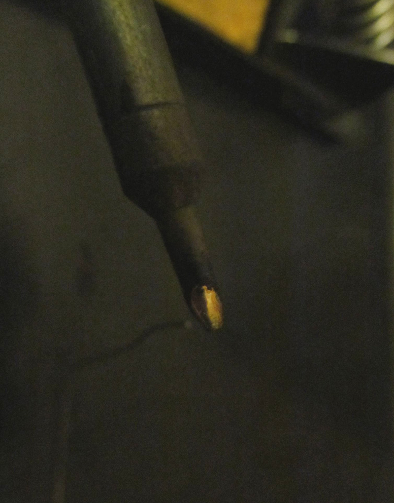 Assuming your soldering iron is at operating temperature pick it up and gently feed solder onto the tip until it melts, I suggest a liberal covering initially and then maybe rub the tip gently on the damp foam pad to remove excess solder. A thin coating is sufficient, big blobs are not required and hinder. This process ‘tins’ the iron itself. This photo (on right) shows an ideal quantity of molten solder on the tip (also known as soldering bit).
Hold the connector firmly with your ‘3rd hand’ helping tool or a pair of pliers with an elastic band around the handle. Hold your soldering iron in one hand and a length of straight solder (10cms is usually appropriate) in your other hand. Then place the tip of the iron onto the bottom of one of the solder tags on the connector and allow the iron to heat the tag for around 3-4 seconds then gently feed solder onto the tag. (Note : do not feed solder onto the tip of the iron).
The goal here is to heat the tag to a high enough temperature for the solder to melt virtually upon contact with the tag, this way the molten solder will gently flow of it’s own accord onto the tag. Feed a few millimeters of solder onto the tag. If the solder does not melt and flow it means you have not successfully heated the tag up. Clean your iron, ‘re-tin’ it well and try again ensuring ample pressure is applied to the tag so heat can be transferred.
 Remember: all importantly feed the solder onto the tag, it can be helpful if you put the soldering iron tip a little down from the place where you wish for solder to tin the tag. Always ensure you have sufficient tinning of the iron itself as solder will not easily flow. You can see the solder on the iron as a conduit for the heat to transfer onto the surface you wish to tin.
Repeat the tinning process with all 3 connector tags, the tinning should leave a nice shiny (or matt with modern lead free solder) thin coat of solder on the surface. As you become more acquainted with tinning you will be able to tin with greater and greater accuracy and use less solder.
Turn your attention to the cable and twist the insulation free earth copper into 1 single strand. You can then tin each of the 3 internal copper cables, 2-3 mm of tinning is usually adequate. Tinning the cable can be a little tricky as there is less surface area to tin. I suggest tinning your iron and applying the tip to one side of the exposed copper strands and feed the solder onto it from the opposite side.
Important: Once all the connections are tinned make sure you put the connector cover and any plastic insulating covers on the cable. If you solder the connector on and forget this, it will possibly mean de-soldering the joints and redoing them. (if you have soldered the connector on the other end of the cable)
Making the connections
By tinning the connections in advance it should make the actually bonding process as easy as mating the tag and tinned copper together and applying heat from the soldering iron tip. However in some instances there will be insufficient tinning so follow this:
Clean your iron tip on the sponge, tin the iron then take the iron in one hand apply heat to the tag on the connector and apply the tinned copper cable to the heated tag, the existing solder will melt / flow and bond. In some instances, you may need to feed some additional solder into the heated joint in order to make a stronger bond.
Repeat this for all connector tags / internal copper cables.
Is the solder joint OK?
A good solder joint is normally one that looks quite smooth and does not have strands of copper fraying off or excessive ‘blobs’ of solder. In the days when lead solder was prevalent a shiny liquid looking texture would be a good sign. Lead has been banned in modern solder and as such it produces a matt silvery grey colour. Visually inspect and pull the cable a little to ensure there is a good connection. Pull any housing insulation over the exposed internal solder connections and screw the housing onto the connector.
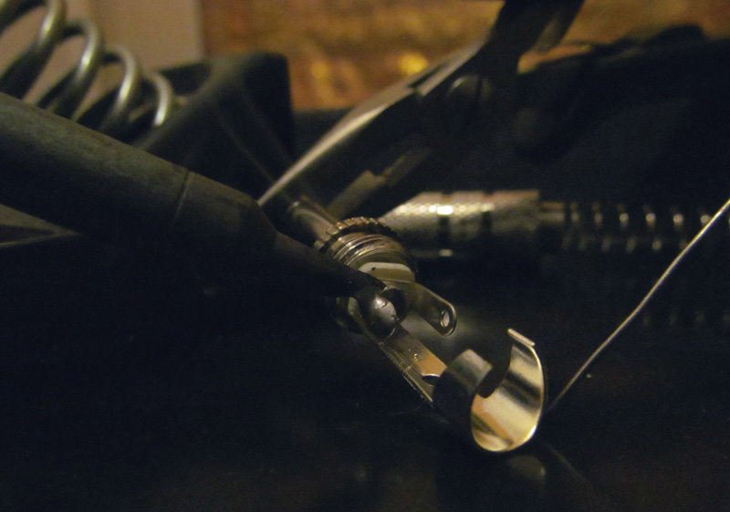
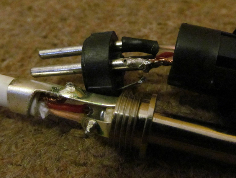 You can use the cable itself and see if it works or as a good secondary check use a multimeter continuity check (beeps when a conductive circuit exists) or use a specifically made cable tester. Here are examples of good and bad soldering joints (photo on right). The TRS jack has shinier and well bonded looking joints and the XLR solder has a grey tarnished look and the wire ill fits the solder tag / well connection.
Tips and summary
- Regularly clean your soldering iron tip and re-tin the tip, this helps keep heat exchange efficient.
- Some of the skill in soldering is about feel, remember you always feed the solder to the parts being soldered not the iron tip itself (unless tinning the iron). Take care not to over heat a cable or tag otherwise it can cause the insulation to melt and burn, this produces a very unpleasant plastic smoke which you should avoid inhaling.
- Unplug the iron without fail every time you leave the room and ensure it is secure in it’s holder.
- Make a habit of specifically looking for a coiled cable, mains plug and iron in one visual field each time you complete a soldering job to ensure you have pulled it out of the mains. Soldering irons can and do cause fires so be extremely vigilant.
Soldering is a very useful skill that all audio engineers and home studio owners should be able to perform. It can also lead to more electronic projects, spur an interest in electronics, and be put to use in many different ways. Repetition is the way to hone your tinning skills, soldering accuracy, steadiness of hand and skill in applying the optimal amount of solder for a job.